May 2019
The Thing I Made
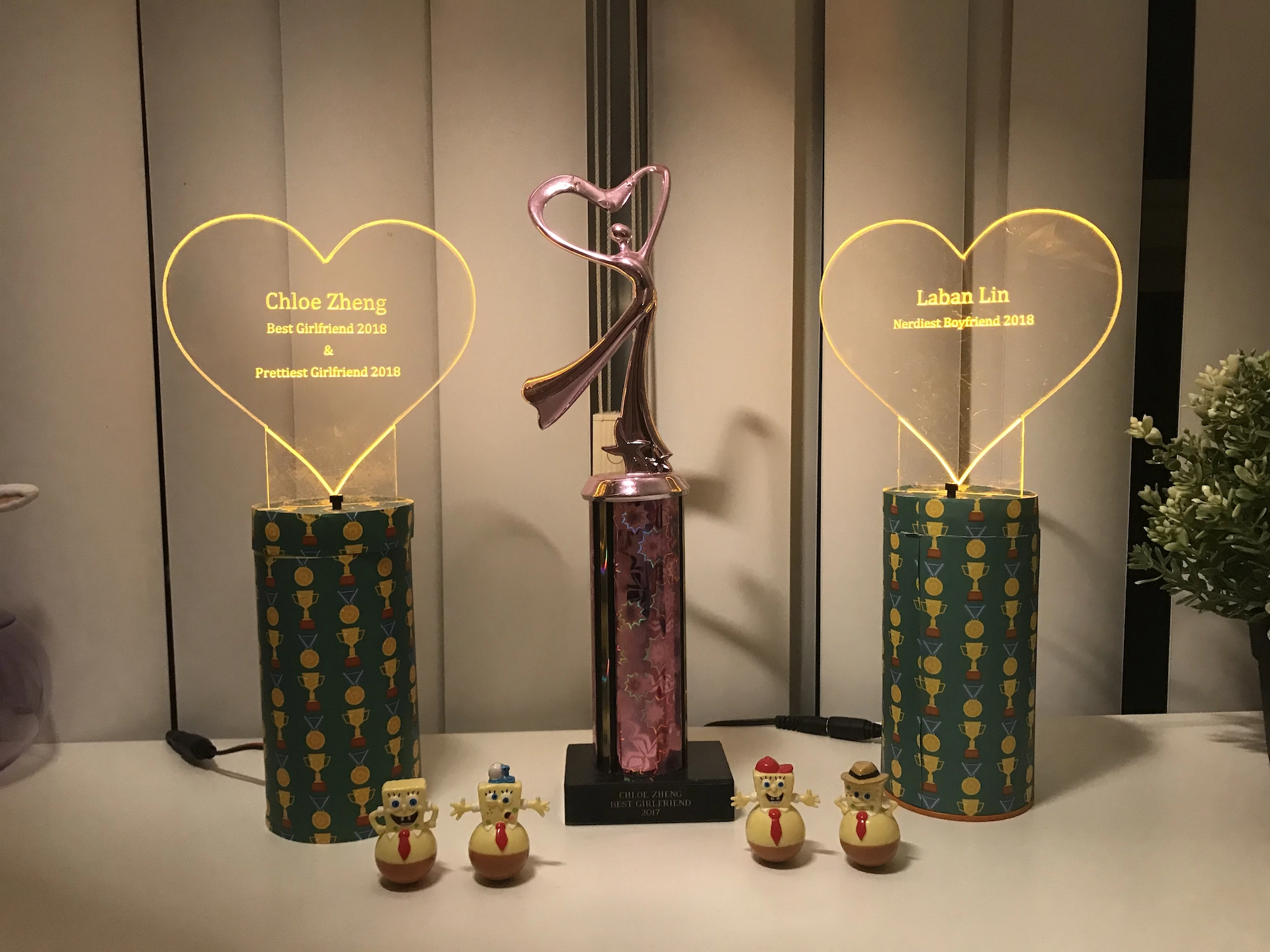
My girlfriend and I have an inside joke: once upon a time, she made a remark about becoming a trophy wife, and I thought it would be funny to give her an actual trophy. This made her the (proud) owner of the (coveted) Best Girlfriend 2017 award. Then 2018 came, and I thought - Oh man - what do I get her this year? Maybe I could up the ante by making a trophy for her instead of buying one.
A while back, I had seen this tweet:
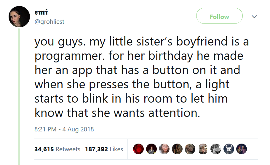
I thought this was such a cute idea, but I wanted to make some changes. I decided to make two trophies - one for me, one for her - and when one trophy’s button is pressed, the other trophy would light up. This would also be more fun for me, because I didn’t have any experience working with hardware.
But before we get too far in, here’s a short clip of the final product:
Architecture
Software
Since we were going to be long-distance that year, the trophies couldn’t be entirely peer-to-peer (e.g. Bluetooth-only), and connections had to be orchestrated by a server. To manage this, I built a tiny server with two endpoints: one to send a ping, and another to check for pings. That’s actually all there is to this server: there’s not even a database of pings; the server keeps track of that in memory. I figured that this was fine for a server that would only ever be accessed by two trophies; if I decided one day to make a bunch to sell, I could always upgrade the code.
Hardware
*Note: if you know anything in the wheelhouse of electrical engineering, this will probably be really boring, but as a software guy, I had a lot of fun learning about the hardware side of things.
Talking to the Server
First things first: the trophy needs to be able to connect to my server, so it needs an internet connection. I used an ESP8266, which is a networking chip with Wi-Fi and Bluetooth receivers. It’s often used to provide an otherwise unconnected Arduino some network access, but because it has 1MB of flash memory, it can also be programmed as a standalone chip. There are some libraries that make it pretty simple to open a HTTPS connection. Here’s how easy it is:
const char* HOST = "my-server-location.com";

//SHA1 SSL fingerprint to verify SSL connection
const char* fingerprint = "** ** **";

WiFiClientSecure client;
if (!client.connect(HOST, 443)) return;
if (!client.verify(fingerprint, HOST)) return; //See note below
client.print(String("GET ") + "/checkForPings?trophyId=1" + " HTTP/1.1\r\n" +
  "Host: " + "my-server-location.com" + "\r\n" +
  "Connection: close\r\n\r\n"); //GETS this url

client.readStringUntil("\n"); //to read each response line

/*
Note: When SSL certificates are rotated, the fingerprint
associated with the website will change and this code (using
a hard-coded fingerprint) will stop working. Currently the
ESP8266 doesn't seem to have a library to verify certificates
automatically, so I've elected to proceed with code execution
no matter what client.verify() returns given there is no
sensitive information transmitted.
*/
Turning on the lights
The next step is to make the ESP8266 actually turn on lights. My first approach was connect LEDs to the output pin of the ESP8266 like so:
const int LEDPIN = 3;
OFF:
digitalWrite(LEDPIN, LOW);
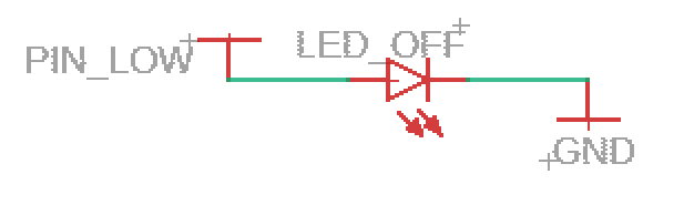
ON:
digitalWrite(LEDPIN, HIGH);
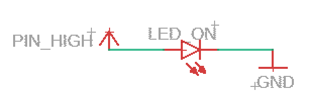
This works! And it makes sense why: when the output is HIGH, the ESP8266 is providing 3.3V to the LEDs, which light up.
There’s a problem, however: the LEDs require 80mA, but the ESP8266 is recommended to only supply 6mA.
We can get around this problem by using a transistor:
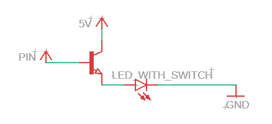
The key part here is the transistor, which will reduce the current drawn from the ESP8266.
Note: If you’ve built a circuit before, you’ll notice that these diagrams are sorely missing resistors. I have included them in the final schematic, but left them out for illustration here.
How do we use a transistor?
A transistor has three pins: a collector (connected to a source of power), a base (our ESP8266 chip), and an emitter (the LEDs). In this case, because this is an NPN transistor, when the base is LOW, no current flows to the emitter. When the base is HIGH, current flows from the collector and base to the emitter, which powers the LEDs.
We know the following:
- IE = IB + IC (current at the emitter comes from the base and collector)
- IE = 80mA (required to drive our LEDs)
And we need to ensure that:
- IB <= 6mA (recommended maximum current from the ESP8266)
We can look at a ratio called the DC Current Gain or hFE, which is the collector current divided by the base current (IC/IB). This value is not constant: it can change depending on the current at the base and the voltage, so manufacturers provide data sheets with sample test cases.
This is an example data sheet:
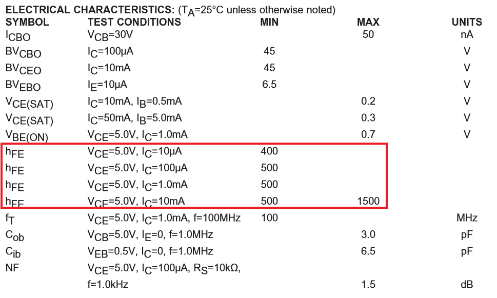
Although there’s no IC = 76mA test case, it looks like assuming hFE >= 400 is reasonably safe.
Thus:
- hFE = IC/IB = 400
- IC = 400 * IB
Recall that:
- IE = IB + IC
So by substitution:
- 80mA = IB + 400 * IB = 401 * IB
- 80mA⁄401 = IB
- 0.2mA ≅ IB
0.2mA is well below the recommended 6mA rating, which means the inclusion of this transistor prevents us from accidentally ruining our chip.
Button Presses
Registering the button presses to turn on the other trophy was fairly straightforward.
I defined an input pin on the ESP8266, and told it to listen to changes in the voltage. This occurred every time I pushed the button, because a depressed button would connect the pin to ground, and cause it to register LOW.
When this happens, we raise a flag in the code.
Then, every few seconds, the ESP8266 checks the flag and if it’s been raised, it talks to the server to let it know the button has been pressed.
//Global Flag
volatile bool sendPulse = false;

//Set Pin 1 as the input pin for the button press
pinMode(1, INPUT_PULLUP);

//Attach event listener
attachInterrupt(digitalPinToInterrupt(1), pulsed, CHANGE);

//Event Handler
void pulsed() {
  sendPulse = true;
}

//Main Event Loop
void loop(){
  if (sendPulse) {
    //Set up HTTPS connection and send the ping
    sendPulse = false;
  }
  //Do other stuff in the event loop
  //Sleep for a few hundred milliseconds
}
Trophy Design
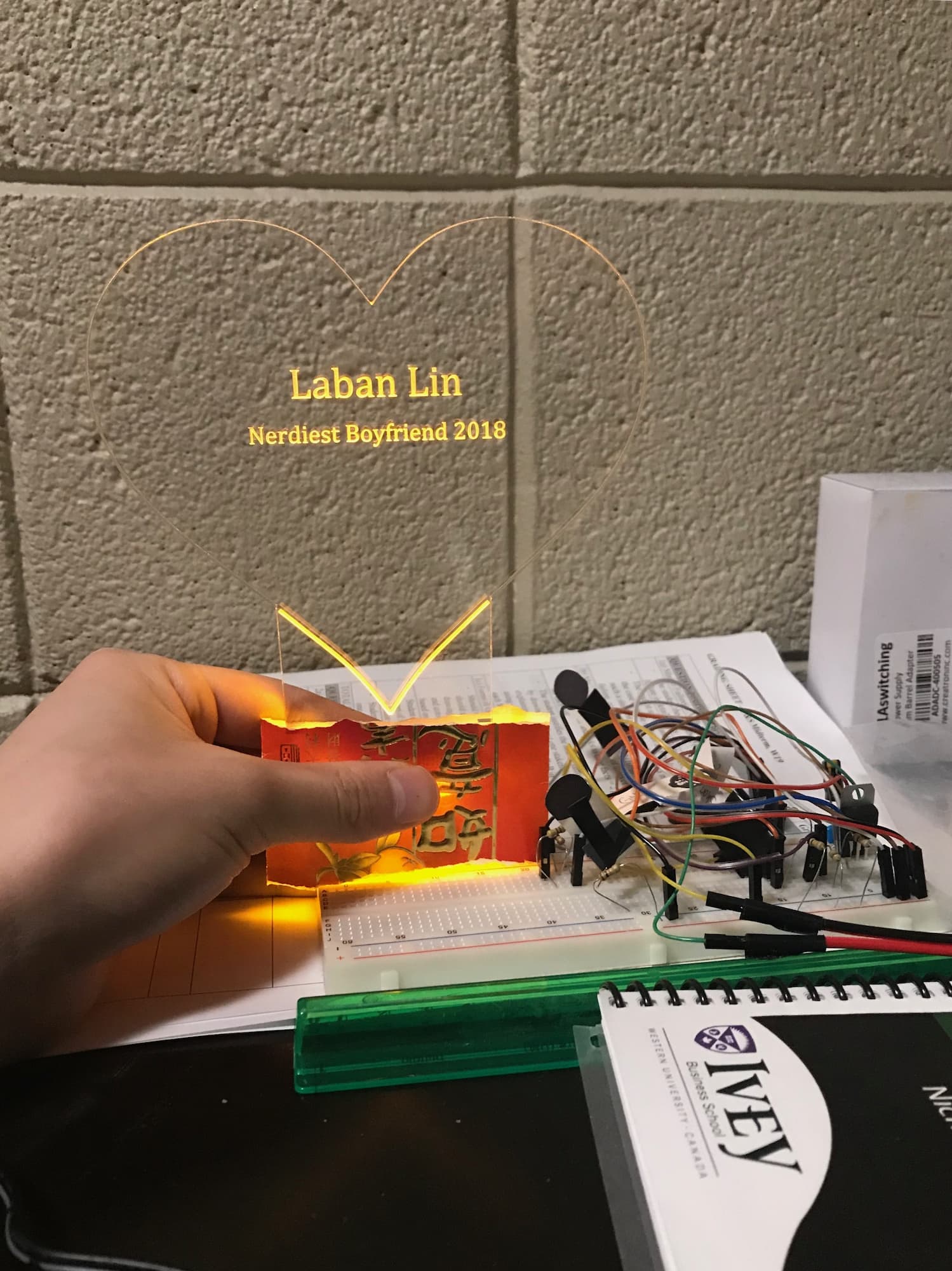
At this point, I had all the core features working on a breadboard, and my chip could do the following:
- Receive button presses and send a ping to the server for the other trophy to receive
- Check the server every 5 seconds for a ping from the other trophy
- Turn the lights on and off for 10 seconds at a time
The next step would be to migrate my circuit from a breadboard to a dedicated circuit board. But first, I had to figure out the physical trophy design - this would inform the dimensions of the circuit board.
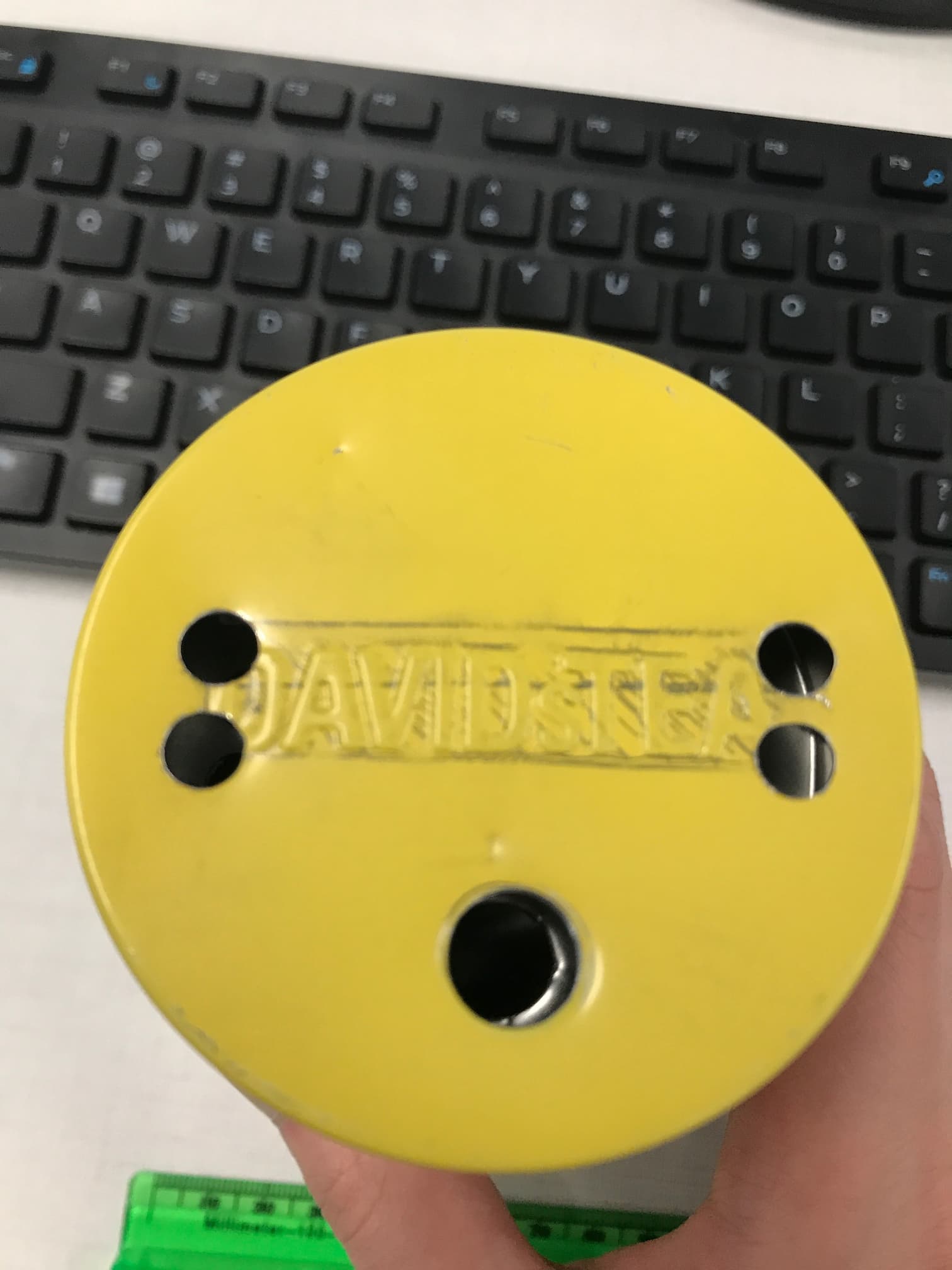
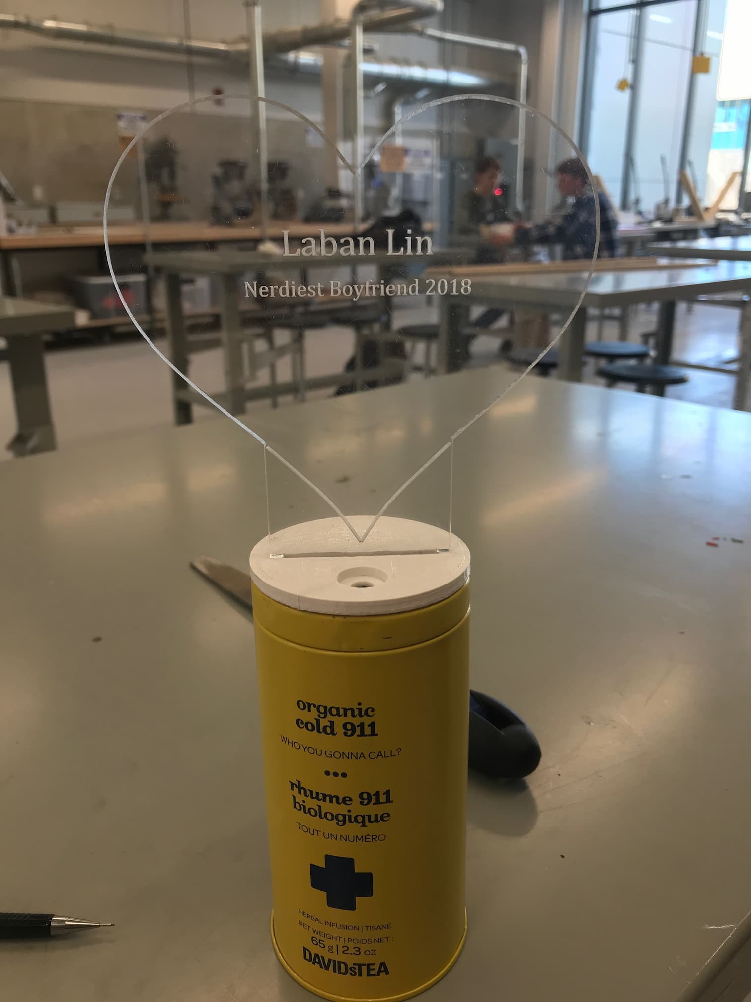
I went through a bunch of potential designs, but I settled on an acrylic heart sat upon a David’s Tea container. This was a fairly shoddy mockup, I’ll admit, but I thought it was fairly promising.
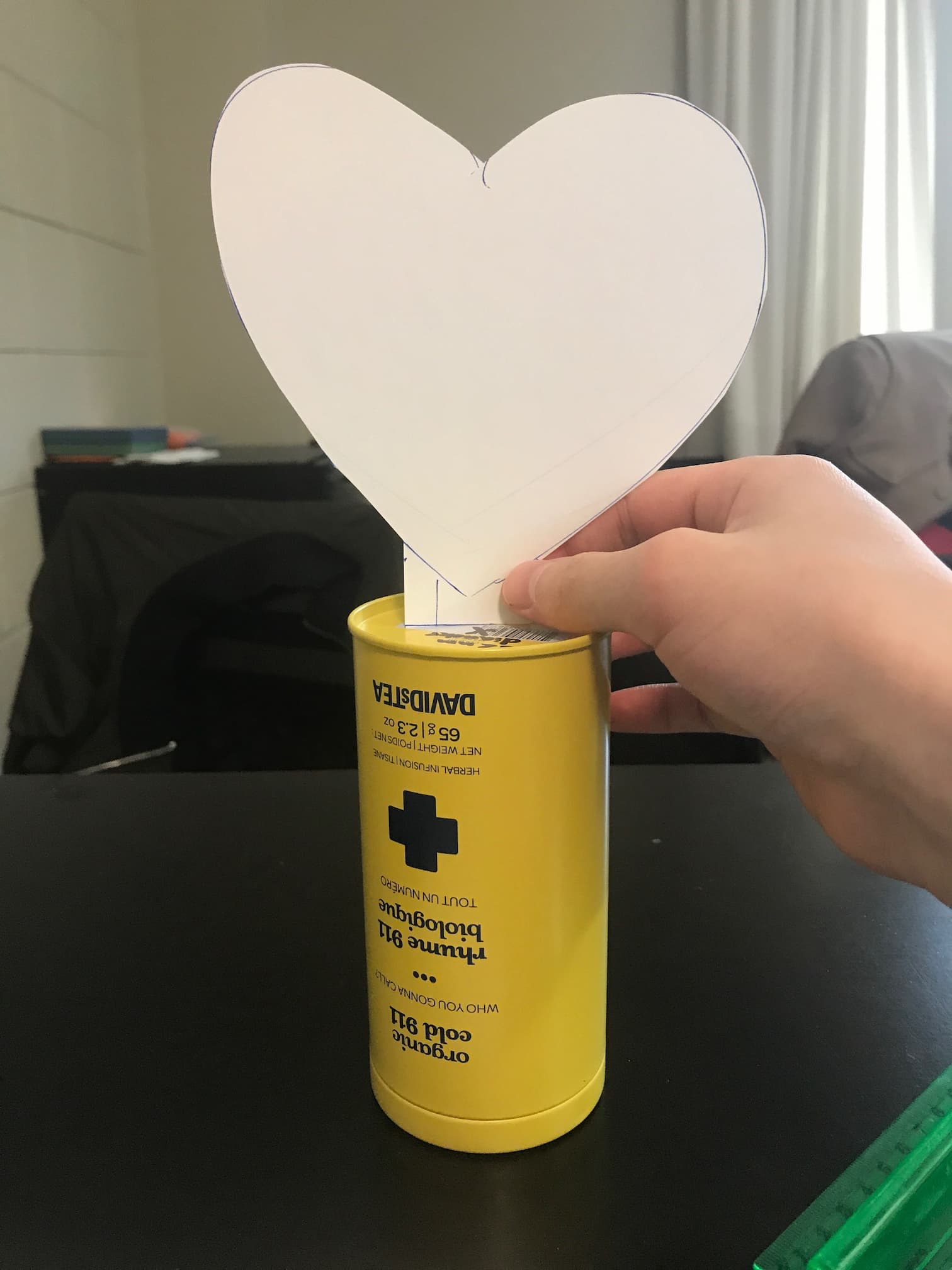
In this design, the acrylic heart would extend inside the tea container, where the circuit board would be hidden. This meant I had to get my design onto a board that was at most 5cm wide, or else it wouldn’t fit.
Circuit Boards
Some hobbyist friends helped me get set up with EagleCAD, in which we made this schematic:
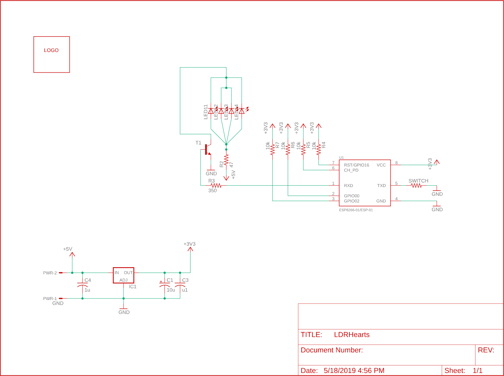
We turned this into a board fairly easily: once the schematic is in place, EagleCAD lets you drag and drop components onto the board design and draw the connecting circuit paths as required. One tip that I got was to use the ratsnest feature. This basically draws an area that is one giant circuit path, which is really useful because it means once you draw the lines connecting your power, ratsnest can immediately ground all the remaining pins on the board.
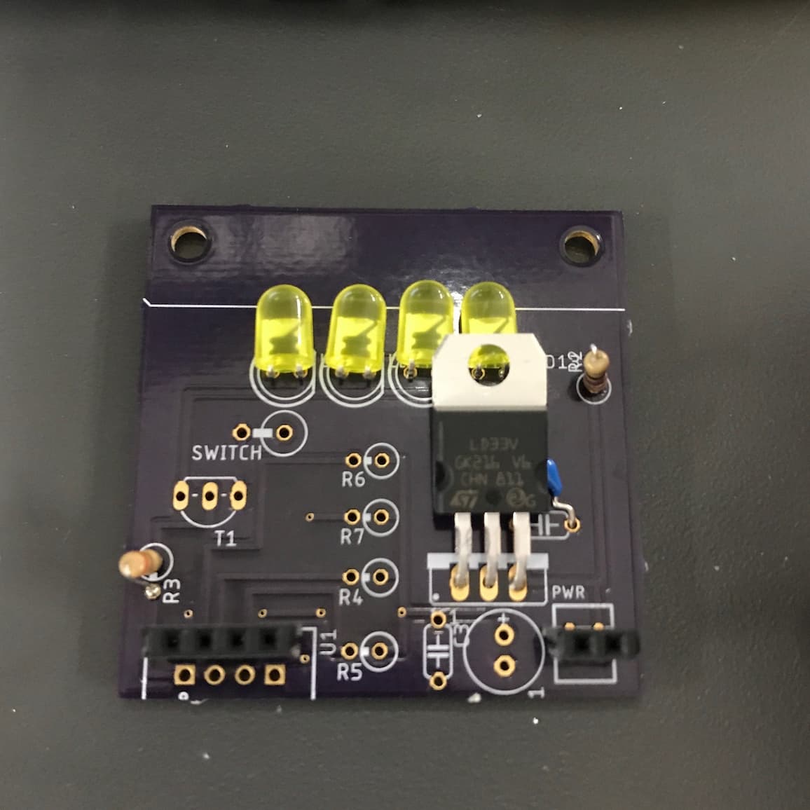
I also drew an outline of my last name in Chinese (林) just for decoration - if you look closely, you can see it on the actual board.
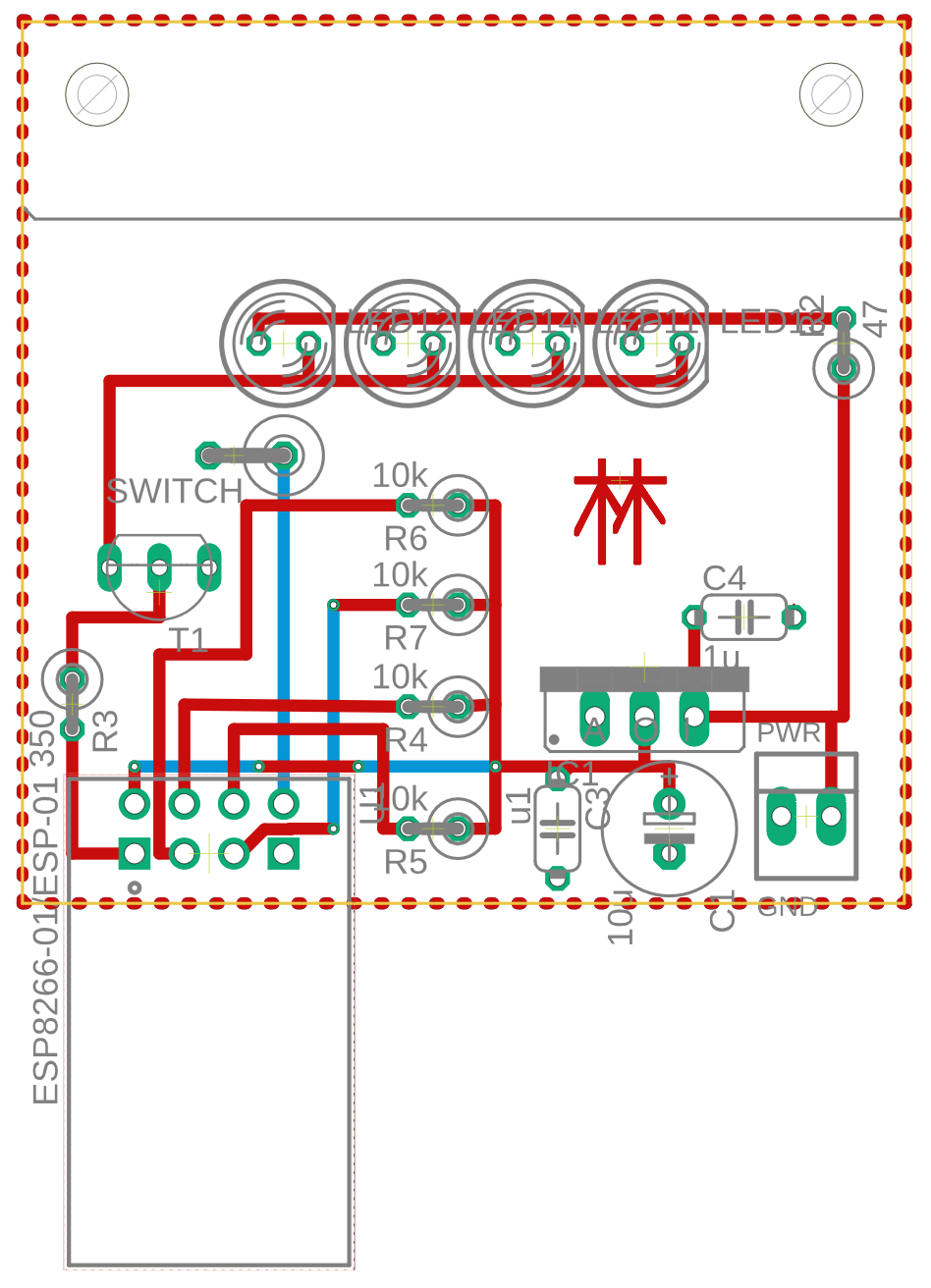
Notice the holes in the upper left and right corners: those were drawn in so I could mount the board and its lights directly below the acrylic heart, so the light would shine directly into the material.
Miscellaneous
- Acrylic Laser-Cut Heart: I learned to use SolidWorks just enough to make a drawing of the acrylic hearts. My school’s laser cutter was set up to accept a SolidWorks drawing and engrave/cut based on line thicknesses and colors. This was a fairly straightforward (though glacial) process; I just didn’t really understand the SolidWorks UI.
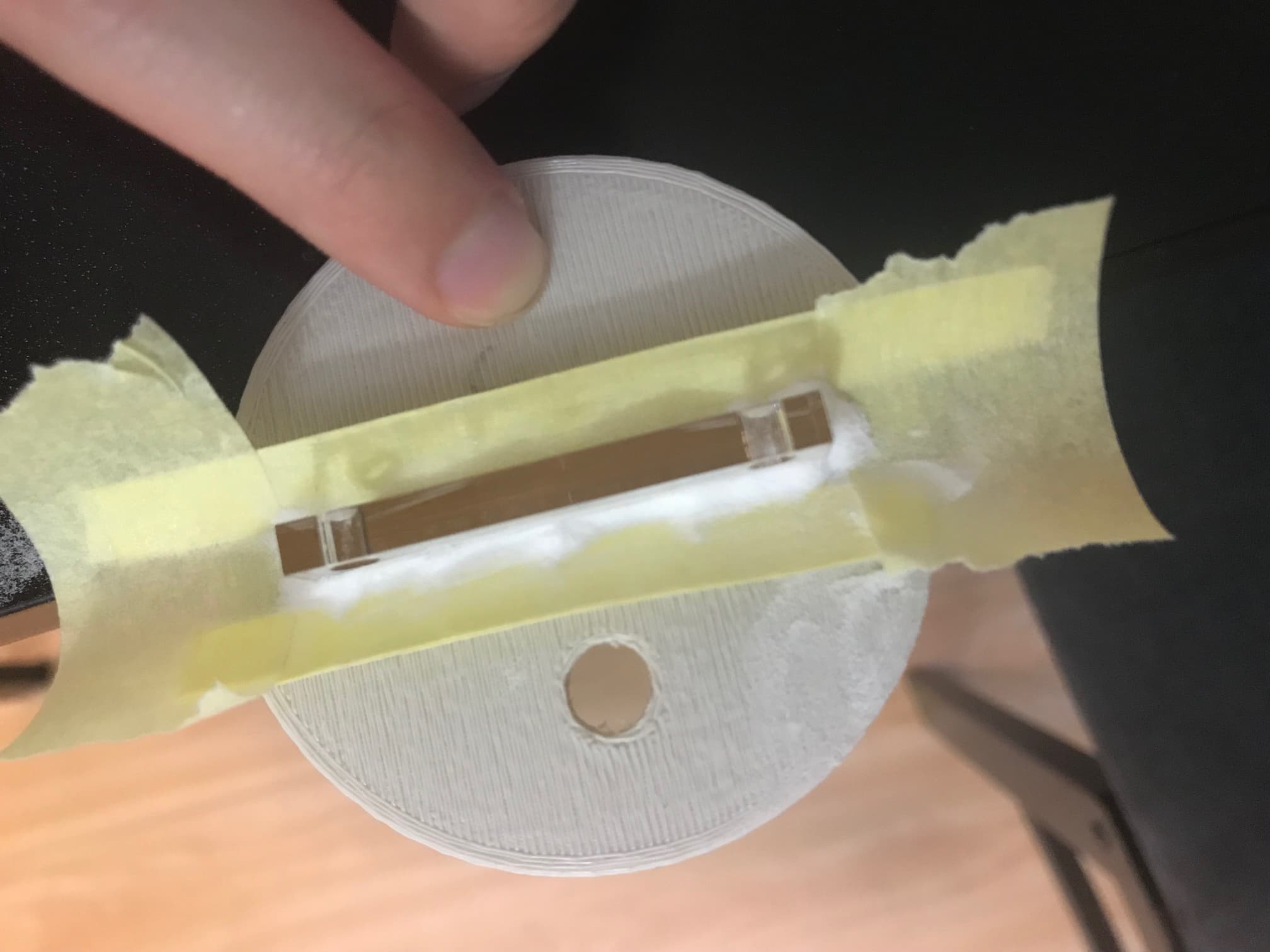
- 3D-Printed Base: For reasons that I’ll never know, the school’s laser cutter caught on fire at an inopportune time: after I’d cut the hearts, but before I’d cut the circular base to mount the hearts to. This was actually a blessing in disguise - I 3D-printed the base instead, which made it easier to undersize the slot for the heart and file it down to ensure a tight fit.
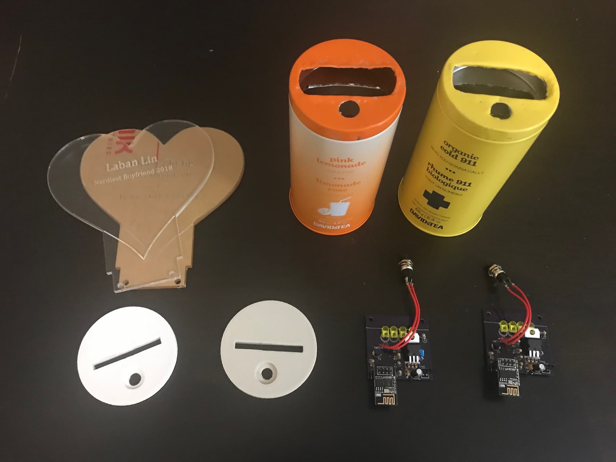
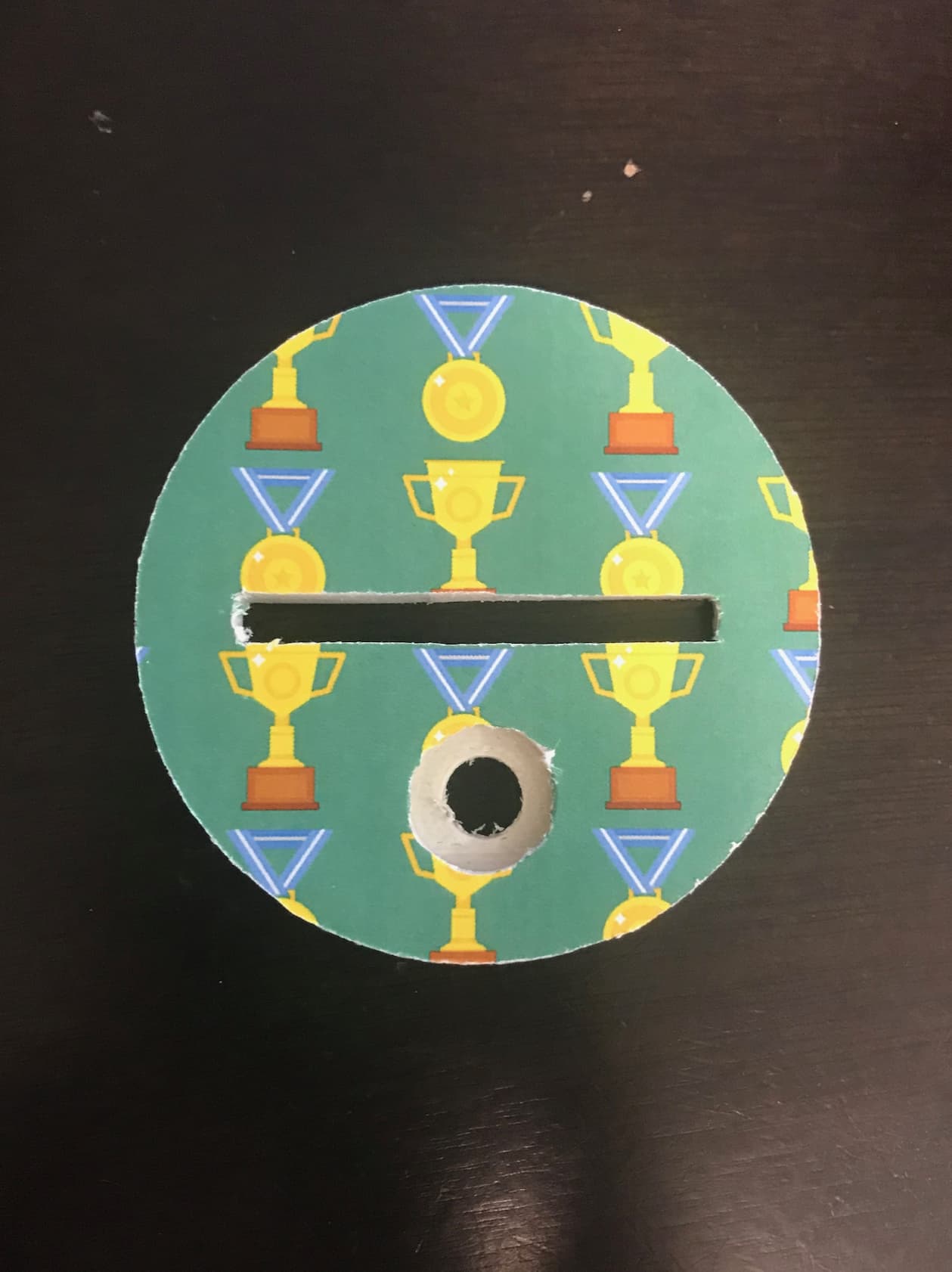
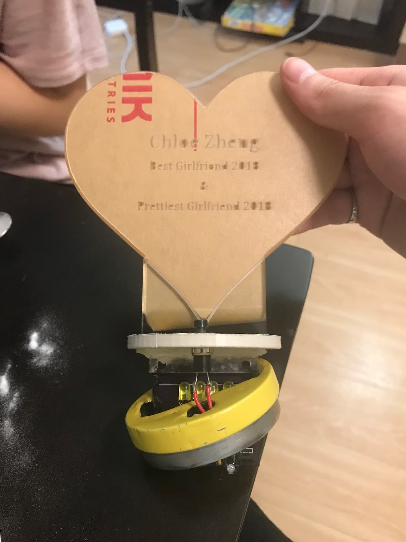
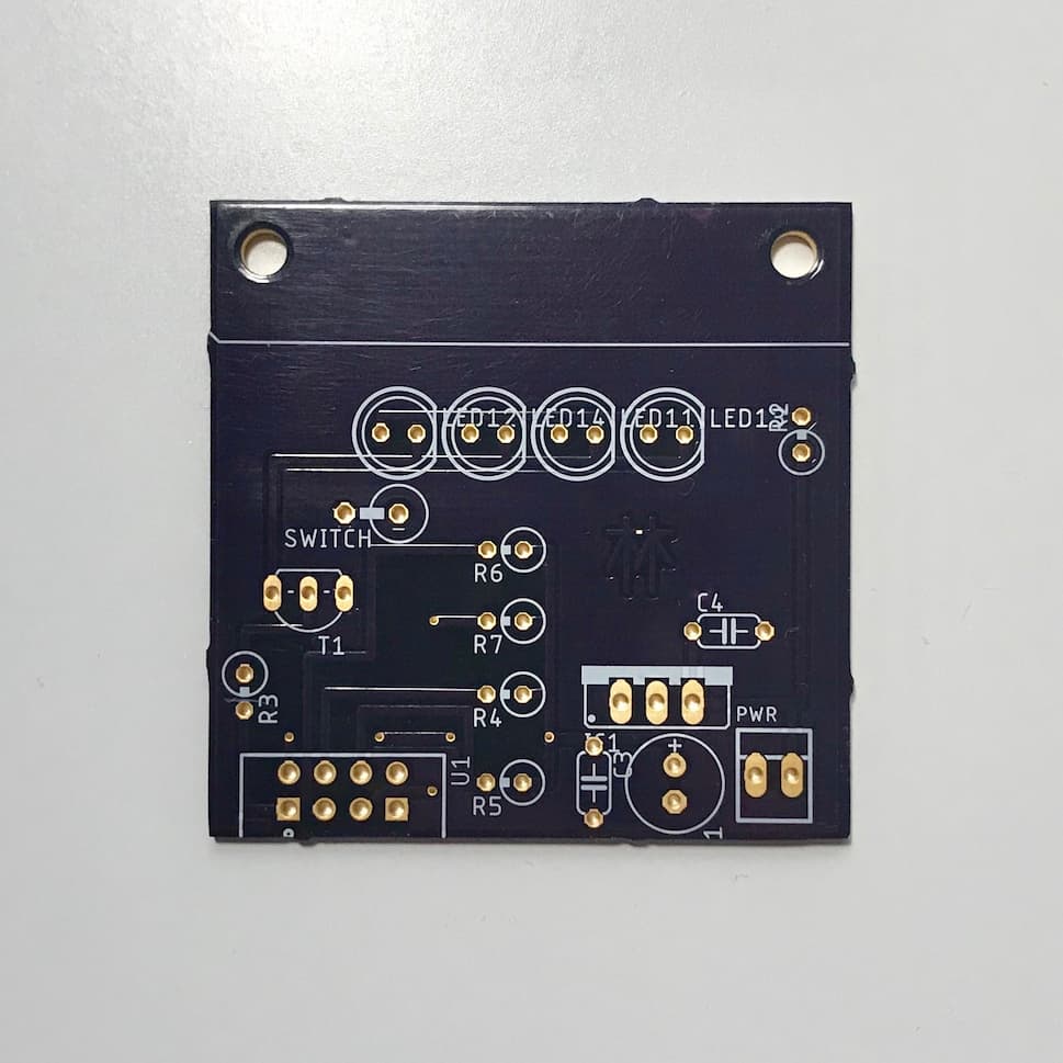
Final Product and Fabrication Process
I forgot to carefully document every step of the fabrication process, so this is a loose collection of images at various stages of the process from start to finish.